Club Scuderia
-
Please take a minute to read this thread about our recent server issues and forum platform Switch
You are using an out of date browser. It may not display this or other websites correctly.
You should upgrade or use an alternative browser.
You should upgrade or use an alternative browser.
Ferrari 348 engine bay and rear end restoration.
- Thread starter Pangea
- Start date
Pangea
Active member
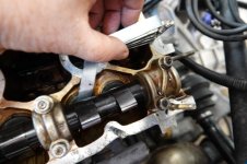
Strip down. Water pump assy and housing, cam belt and tensioners, belt covers cam covers and cam shafts. I cant really fault the water pump bearings or the cam belt tensioner bearings. Perfectly smooth and no play but I am replacing both items this time. Always the chance of a leak from an old pump. All looks well in the cam area with no wear or marking on any components. Cam carriers very good. Before taking the cams out I checked the valve clearances as its easy to pop in a new size shim with the them out if you dont have the tools handy for cams in. I dont have to worry this time.
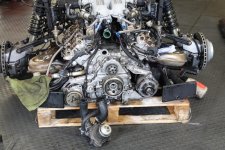
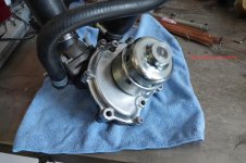
New pump on housing.
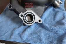
New o ring to rear flange of water pump housing. You dont want a leak from that area.
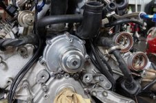
New water pump installed. I was expecting some snapped studs or bolts here but it all came undone without issue.
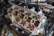


New pump on housing.

New o ring to rear flange of water pump housing. You dont want a leak from that area.

New water pump installed. I was expecting some snapped studs or bolts here but it all came undone without issue.

Pangea
Active member
CAM SEAL REMOVAL.
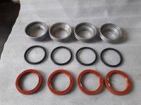
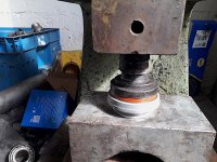
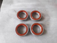
So here we have the infamous 348 cam seals. Notorious for leaking, more often than not the bank 1-4 exhaust cam, but Ive not found that to be a problem. Anyway its probably good practice to renew them when doing the belt service along with the large carrier O rings. Removing the seals from the carriers is a bit of a challenge as I woulnt want to be squeezing them in a vice or the like really. I fell lucky here as I was looking for a solution and picked an old bearing case, kept as useful tooling for the press. Just so happens that the carriers were a perfect fit and just sat on a seal ridge in the bearing case. Thin punch and hammer and out they came. The vice could then be used as a support and I found this easier than on the bench. Not a mark on the carriers. New they are £611 + vat each by the way....
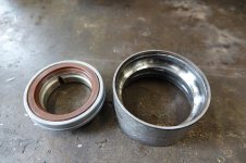
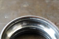
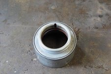
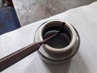
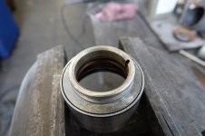
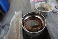
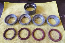
So here we have the infamous 348 cam seals. Notorious for leaking, more often than not the bank 1-4 exhaust cam, but Ive not found that to be a problem. Anyway its probably good practice to renew them when doing the belt service along with the large carrier O rings. Removing the seals from the carriers is a bit of a challenge as I woulnt want to be squeezing them in a vice or the like really. I fell lucky here as I was looking for a solution and picked an old bearing case, kept as useful tooling for the press. Just so happens that the carriers were a perfect fit and just sat on a seal ridge in the bearing case. Thin punch and hammer and out they came. The vice could then be used as a support and I found this easier than on the bench. Not a mark on the carriers. New they are £611 + vat each by the way....


milkshaker0007
Active member
Same as the 328, O ring and seal. Same leaking design.
I wish I had a press when I did mine, had the use two pieces of wood and squeeze together in my workshop vice.
I’m sure you know but make sure those valleys line up the oil return hole in your engine block, as they easily turn when you put your cam covers back on, and can be out of alignment, found that one out twice now, so mark edge of ring and block with marker pen.
Pangea
Active member
Same as the 328, O ring and seal. Same leaking design.
I wish I had a press when I did mine, had the use two pieces of wood and squeeze together in my workshop vice.
I’m sure you know but make sure those valleys line up the oil return hole in your engine block, as they easily turn when you put your cam covers back on, and can be out of alignment, found that one out twice now, so mark edge of ring and block with marker pen.
Nothing wrong with the vice and wood method. Without the press that was my next option. As for the oil channels I have already had a look at that. :thumbsup: Made a permanent indicator on the seal carrier. Much as you described. Otherwise you are guessing the position when putting the cams in. My carrier slots were no where near where they should have been for years but the seals didnt leak..Im surprised at that. Ive got some pics. Will post when sorted them out.
Pangea
Active member
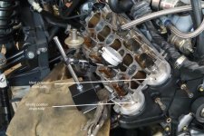
Aligning oil drain holes in the heads with the grooves cut in the cam seal carriers is guess work when installing the cams without some reference marks as your view is obscured . My carriers have a notch cut into the outside rim. Im sure I read it somewhere that this notch had to be lined up with the reference marks on the camshaft and that would line up your groove and drain hole but I cant find that thread now. Anyway, this is nonsense where mine are concerned as they are aligned so Ive recut a mark which you can line up with the flat of the cylinder head and it will be guaranteed to be in the correct place. Few pics to show that. Im sure draining occurs if not in line but it must be more efficient if they are. Im sure Ferrari techs must do the same.....
Pic 1....My original carriers. Pic 2... New reference mark aligned with head. Pic 3...Oil drain groove now guaranteed to line up with hole.. Repeat process for all four cams.
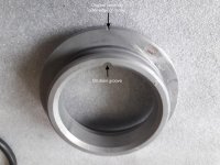
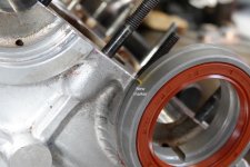
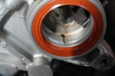
Pic 1....My original carriers. Pic 2... New reference mark aligned with head. Pic 3...Oil drain groove now guaranteed to line up with hole.. Repeat process for all four cams.


irarref
Active member
That looks like you've had the oil drain mod done??? 
Cross reference against pics here:
https://www.ferrarichat.com/forum/threads/328-cam-seal-oil-drain-hole.267158/
Cross reference against pics here:
https://www.ferrarichat.com/forum/threads/328-cam-seal-oil-drain-hole.267158/
Pangea
Active member
That looks like you've had the oil drain mod done???
Cross reference against pics here:
https://www.ferrarichat.com/forum/threads/328-cam-seal-oil-drain-hole.267158/
I dont think so Jeff. The 1/4 bank drain hole is still in the "too high" position but now aligned with the drain groove for sure. The pics above shows the 5/8 bank. Ive lost a thumb drive somewhere with lots of pics and one showing the so called issue. Im sure the new kitten has hidden it.:hmmm: Ive not suffered any leaks though so not too worried about it. Maybe if you run the engine on a regular basis and not let it sit as said in the thread you posted, along with a good quality and condition seal it seems ok. I run it up to temp at least once a month if not more during the SORN periods. Maybe next time its out and if I can get a jig sorted I will address that. Apparently when they do leak its very minor.
irarref
Active member
Ah right I see - Ferrari actually list the tool but not sure whether they have it in stock
https://www.ferrariparts.co.uk/part/ferrari/95845027?id=30724
https://www.ferrariparts.co.uk/part/ferrari/95845027?id=30724
Pangea
Active member
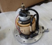
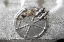
FUEL PUMP 2
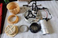
Second fuel pump striped for inspection. As with the first, good condition and no nasty black residue in the filter which could indicate the rubber parts disintegrating.
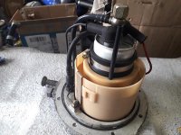
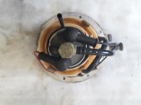
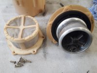
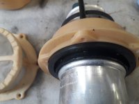
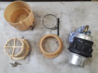
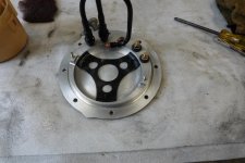
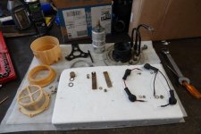
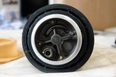
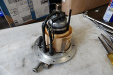
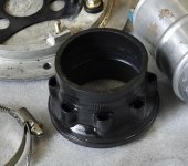
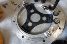
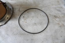
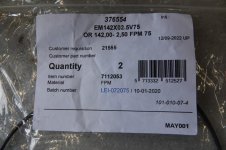
Highly recommend replacing the large O ring sealing the pump to the tank. You can see how they go oversize when released. The new fits perfectly. I sourced these locally and the size I used was 142mm inside diameter by 2.5 mm cross section. Mayday Seals and bearings, Cheltenham.. Around £5 for two.
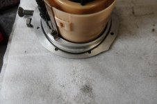
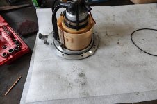
Second fuel pump striped for inspection. As with the first, good condition and no nasty black residue in the filter which could indicate the rubber parts disintegrating.


Highly recommend replacing the large O ring sealing the pump to the tank. You can see how they go oversize when released. The new fits perfectly. I sourced these locally and the size I used was 142mm inside diameter by 2.5 mm cross section. Mayday Seals and bearings, Cheltenham.. Around £5 for two.


Looking good
+1 :thumbsup:
milkshaker0007
Active member
Looking great:thumbsup:

